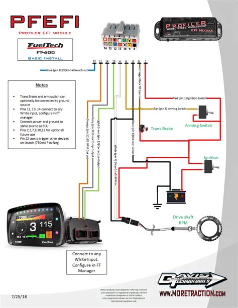
The world of automotive wiring can be overwhelming, especially when it comes to fuel injection systems. However, understanding the basics of fuel tech wiring diagrams can make a huge difference in troubleshooting and repairing your vehicle. In this article, we'll break down the components and connections of a typical fuel tech wiring diagram, making it easier for you to comprehend and work with.
What is a Fuel Tech Wiring Diagram?
A fuel tech wiring diagram is a visual representation of the electrical connections and components that control the fuel injection system in your vehicle. It's a blueprint that shows how the various sensors, actuators, and computers work together to manage the fuel delivery process. By studying a fuel tech wiring diagram, you can gain a better understanding of how your vehicle's fuel system operates and identify potential problems.
Components of a Fuel Tech Wiring Diagram
A typical fuel tech wiring diagram consists of several key components, including:
- Engine Control Module (ECM): The brain of the fuel injection system, responsible for processing data from various sensors and controlling the fuel injectors.
- Fuel Injectors: Electrically controlled valves that spray fuel into the engine's intake manifold.
- Fuel Pressure Sensor: Monitors the fuel pressure in the system and sends data to the ECM.
- Throttle Position Sensor (TPS): Measures the throttle valve's position and sends data to the ECM.
- Mass Airflow Sensor (MAF): Measures the amount of air entering the engine and sends data to the ECM.
- Coolant Temperature Sensor: Monitors the engine's coolant temperature and sends data to the ECM.
Understanding the Wiring Diagram
A fuel tech wiring diagram typically uses a combination of symbols, colors, and lines to represent the various components and connections. Here's a brief explanation of the most common elements you'll encounter:
- Lines and Wires: Represent the electrical connections between components. Solid lines usually indicate a direct connection, while dashed lines may indicate a connection through a relay or other device.
- Symbols: Used to represent components, such as sensors, actuators, and computers. Common symbols include rectangles for sensors, circles for actuators, and triangles for computers.
- Colors: Used to differentiate between different types of wires or connections. Common colors include:
- Black: Ground wires
- Red: Power wires
- Yellow: Signal wires
- Green: Sensor wires
- Blue: Actuator wires
How to Read a Fuel Tech Wiring Diagram
To read a fuel tech wiring diagram, follow these steps:
- Identify the Components: Look for the symbols and labels that represent the various components, such as the ECM, fuel injectors, and sensors.
- Follow the Wires: Trace the lines and wires that connect the components, taking note of the colors and symbols used.
- Understand the Connections: Identify the connections between components, including the type of connection (direct or through a relay) and the wire color.
Practical Applications of Fuel Tech Wiring Diagrams
Understanding fuel tech wiring diagrams can help you in several practical ways:
- Troubleshooting: By studying the wiring diagram, you can identify potential problems and pinpoint the source of issues.
- Repairs: Knowing how the components and connections work together can help you make repairs more efficiently.
- Upgrades and Modifications: A fuel tech wiring diagram can help you plan and execute upgrades or modifications to your vehicle's fuel system.

**Fuel Tech Wiring Diagram Symbols and Abbreviations**
Here are some common symbols and abbreviations used in fuel tech wiring diagrams:
- ECM: Engine Control Module
- FUEL: Fuel injector
- FPS: Fuel pressure sensor
- TPS: Throttle position sensor
- MAF: Mass airflow sensor
- CTS: Coolant temperature sensor
- GND: Ground
- V: Voltage
- AMP: Amperage
**Fuel Tech Wiring Diagram Color Codes**
Here are some common color codes used in fuel tech wiring diagrams:
- Black: Ground wires
- Red: Power wires
- Yellow: Signal wires
- Green: Sensor wires
- Blue: Actuator wires

**Conclusion**
In conclusion, understanding fuel tech wiring diagrams can seem intimidating at first, but by breaking down the components and connections, you can gain a better understanding of how your vehicle's fuel system operates. By studying a fuel tech wiring diagram, you can identify potential problems, make repairs more efficiently, and plan upgrades or modifications. Remember to take your time, follow the wires, and understand the connections to become proficient in reading fuel tech wiring diagrams.
Call to Action
If you have any questions or need further clarification on fuel tech wiring diagrams, please leave a comment below. Share this article with your friends and fellow car enthusiasts to help them better understand their vehicle's fuel system.


What is a fuel tech wiring diagram?
+A fuel tech wiring diagram is a visual representation of the electrical connections and components that control the fuel injection system in your vehicle.
How do I read a fuel tech wiring diagram?
+To read a fuel tech wiring diagram, identify the components, follow the wires, and understand the connections between components.
What are the common symbols and abbreviations used in fuel tech wiring diagrams?
+Common symbols and abbreviations include ECM, FUEL, FPS, TPS, MAF, CTS, GND, V, and AMP.
